Files in, files out
DXF nesting: what goes in and what comes out
Nest&Quote nests parts from DXF drawings and TRUMPF GEO files. This page sets out which files it reads, what you can take away from a nest today and what comes after that. Each item carries one of three labels:
- Available: in the product today.
- Available, dry run first: in the product today, and not yet confirmed on a shop's controller. Check every program before you cut with it.
- Planned: on the list, with no date yet. The order follows what shops ask for.
| What | Status |
|---|---|
| DXF drawings or TRUMPF GEO files, one part per file | Available |
| Print sheets, on paper or saved as a PDF | Available |
| Nested DXF, one file per sheet | Available |
| One DXF with every sheet of the job | Available |
| Cutting paths: kerf compensation, lead-ins, cut order | Available |
| Machine programs in G-code: generic (M3/M5), EIA RS-274D (M07/M08), GRBL laser | Available, dry run first |
| Plasma: small holes with reduced feed and overburn; QtPlasmaC syntax; touch-off and THC in the program (G31, Z) | Available, dry run first |
| Router programs: spindle, depth passes, holding tabs | Available, dry run first |
| More controllers | Planned |
The rules a drawing has to meet
Status: available
- DXF or GEO, up to 5 MB per file. DXF R12 and every version from 2000 to 2018, text or binary, and TRUMPF GEO files from TruTops. DWG and STEP are not read; export a DXF from your CAD, as you would for the machine.
- One part per file. The file name becomes the part code, and you can change it. If a file holds more than one part, the largest is nested, the result says so and you can choose another outline and nest again.
- Drawing sheets. A frame with a title block is recognised and left out, together with boxed views. The 1:1 outline beside the sheet is nested if there is one; otherwise the largest view, marked for you to check. Material and thickness are read from the drawing's text and compared with the job.
- Units come from the file. A drawing saved in inches, feet, centimetres or metres is converted to millimetres. A file with no units set is read as millimetres. R12 files cannot store units, so they are always read as millimetres: a part drawn in inches and saved as R12 comes in 25.4 times too small.
- Closed outlines. Every part needs a closed outer contour. Closed contours inside it become holes, whatever their size. Lines, arcs and polylines whose ends meet are joined into one outline, so a part drawn as loose lines still counts as closed. A contour that does not close is ignored, and the result counts how many were ignored.
- Curves and blocks. Arcs, circles, ellipses, splines and polylines with arc segments are all read. Blocks are exploded, so a part drawn as a block is read like any other geometry.
- What is ignored. Text, dimensions, leaders, hatches and points, and the layers for dimensions, text, titles, hidden and centre lines, by their English, German and Italian names. Dashed lines are not cut. Lines drawn twice count once. A line that is not part of a closed outline is ignored and counted as an open contour.
- Bend lines. Lines on a bend layer, dashed lines across the part and straight lines from one point of the outline to another are counted as bends, not cut. The count is shown with the part.
- Marking. Lines on a marking layer (mark, etch, engrave, scribe, Gravur, Markierung, Signierung …) are the part's marking: never cut and never a hole, drawn on the nest and priced as marking time.
- Edit part. Under each part, Edit part shows every line of the drawing by what it became. Give lines or whole layers another role (cut, mark, bend line, ignore), pick the outer contour, turn the part or set the units, check the part's figures, and nest again.
- Smallest part. A part needs at least 4 mm² of material, a 2 mm square. Smaller closed shapes outside a part are taken for stray marks. A file with nothing larger is listed under Not nested with the reason.
- Wider than every sheet. A part that does not fit inside the edge margin of any sheet size you entered is not nested. It is listed under Not nested with its size.
When a file breaks one of these rules, the result names the part and says what happened.
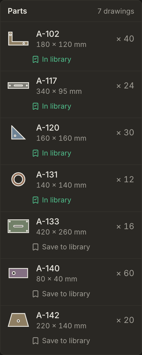
Preparing a DXF for cutting goes through each note and how to fix it.
Print the sheets
Status: available
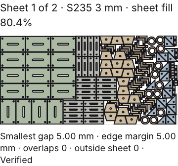
Print sheets opens your browser's print dialog with every sheet of the job on its own page. Each page gives the sheet number, the material, the thickness and how much of the sheet is parts, with the nest drawn over the whole sheet. Where a sheet leaves a remnant, it is shaded and labelled with its size.
Most browsers can save the pages as a PDF from the same dialog, for the job folder. The print is for the floor and the office. For the cut file, download the DXF.
Nested DXF files for your CAM
Status: available
Next to the sheet tabs of a finished job, Cut file (DXF) offers two downloads:
- Sheet n: the sheet on screen in its own file, with every part in its nested position and rotation.
- All n sheets: every sheet of the job in one file, side by side, each titled with its number and size.
What the files contain:
- Geometry in millimetres, at 1:1. Holes that are circles come out as true circles; other curves as fine polylines, within 0.02 mm of the drawing.
- Each part code on its own layer, in red. The sheet outline (SHEET, grey), the usable area inside the edge margin (USABLE_AREA, grey and dashed) and, on the last sheet, the remnant (REMNANT, cyan) sit on layers of their own, so you can switch off what should not be cut.
- The part names on a LABELS layer (green), switched off.
- Marking lines on a MARK layer (magenta), so your CAM can give them a marking process or leave them out.
- The outlines as drawn: no lead-ins, no cut order and no compensation for the cut width, so your CAM can set its own. The machine programs below have all three.
Into LightBurn, SheetCAM or Fusion
Status: available
The DXF goes into the software you already run, in three steps each.
LightBurn (laser)
- Use File > Import and pick the DXF of the sheet.
- Measure one part against its drawing. The file is in millimetres.
- LightBurn sorts imported lines into layers by colour. Set the red part layer to cut, and switch output off for the other colours: the sheet outline and usable area (grey), the remnant (cyan) and the labels (green), if they come in. Marking (magenta) gets your marking settings.
SheetCAM (plasma, waterjet, router)
- Use File > Import drawing and pick the DXF of the sheet. Set the units to millimetres in the import options.
- The layers arrive as they are in the file: one per part code, plus SHEET, USABLE_AREA, REMNANT and LABELS, and MARK when the parts carry marking.
- Add your cutting operation to the part layers only. SheetCAM then sets lead-ins and cut order and writes the program through your post-processor, as it does for any drawing.
Fusion, formerly Fusion 360 (router, and any machine you program from Fusion)
- In the Design workspace, use Insert > Insert DXF, choose a plane and set the units to millimetres.
- The sheet comes in as a sketch. Extrude the part profiles to the sheet thickness.
- In the Manufacture workspace, set up your toolpath on the parts, leaving the sheet outline out, and post it as you do now.
Machine programs in G-code
Status: available, dry run first
Every nest comes with its cutting paths. From them, Machine program (G-code) under the sheet writes the program for the sheet on screen.
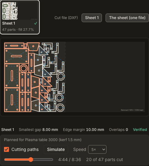
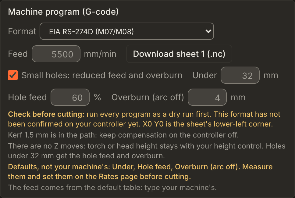
- Formats. Generic G-code, which switches the process with M3/M5, as LinuxCNC and Mach3/Mach4 do. EIA RS-274D, which switches it with M07/M08, as many industrial plasma and waterjet controllers do. GRBL in laser mode, with M4 and a power setting. For plasma also: the QtPlasmaC syntax and touch-off with THC in the program (below). For a router: a router program (below). Set each machine's format under Rates > Your machines; the job page starts with it.
- What is in it. Absolute millimetres from the sheet's lower-left corner. The kerf of the machine the job was nested for is already in the path, so cutter compensation on the controller (G41/G42) stays off. Without a machine, the process you pick when nesting sets a typical kerf and lead-ins instead. A path with no kerf at all is flagged on the page and in the program, because its parts would come out one kerf small. One pierce per contour, holes before their part and parts in cut-outs before the part around them. Round holes come out as full circles and arcs as G2/G3 moves; the rest is straight moves.
- Feed and pierce dwell. These come from the default table for the process, material and thickness until you type your machine's values. The EIA and GRBL formats leave the pierce delay to the controller; in GRBL's M4 mode the laser has no power while the head stands still.
- What is not in it. In the generic, EIA and GRBL formats there are no Z moves: torch or head height stays with your height control. Marking is not in the program yet: mark from the MARK layer of the DXF. A hole too small for the kerf is left out, and the program's header names it.
Plasma: small holes, QtPlasmaC, touch-off
- Small holes. Switch on Small holes for a plasma machine and every hole under a size you set (in mm, or as a multiple of the thickness) is cut at a reduced hole feed. With an overburn length above zero, the arc goes off when the hole closes and the torch keeps moving that far along the hole, with no lead-out, so the dying arc finishes the hole without a notch. The starting values, 32 mm, 60 % and 4 mm, are the defaults the QtPlasmaC manual gives for its own hole cutting, and they are labelled as defaults. THC codes are not written on a small hole.
- QtPlasmaC syntax. Written as the LinuxCNC QtPlasmaC manual documents it:
M3 $0 S1andM5 $0, its metric preamble,M52 P1for velocity changes,M67 E3 Q..for the hole feed andM62 P3/M63 P3for the overburn. There are no Z moves and no dwell: the controller does touch-off, pierce delay and height control from its material table. With a material number set on the machine, the program selects it (M190 P..,M66 P3 L3 Q1) and takes the feed from it. - Touch-off and THC in the program. For controllers where the program drives Z, as Mach3/Mach4-style plasma
set-ups do: at each pierce it rapids at safe Z, probes down with
G31, sets Z at the floating-head switch withG92and the switch offset, goes to pierce height, pierces, dwells and moves to cut height; after the cut it retracts to safe Z. Z0 is the plate top, so set it before you start. Pierce height, cut height, safe Z, Z feed, probe depth and switch offset are set per machine; until you set them the program uses defaults (3.8 mm, 1.5 mm, 10 mm, 500 mm/min, 10 mm below Z0, 1.5 mm) and its header lists every value that is still a default. THC on/off codes and whetherG4 Pcounts seconds or milliseconds differ between controllers, so they are yours to set: empty THC codes are not written. TheG92offset stays active after the program.
Router programs
A router machine gets a program too. The tool is an end mill of the machine's kerf: the paths are already offset by
its radius, so there is no G41/G42 and no tool change; load the tool first. Z0 is the top of the sheet. The spindle
starts once (S.. M3 and a spin-up dwell); each contour is plunged at its lead-in at the plunge feed and cut in
equal passes no deeper than the depth per pass, down to the thickness plus the breakthrough, stepping down in place
at the start of the closed contour. Rapids run at safe Z. With holding tabs on, the tool lifts over a few short
stretches of every outer contour on the passes below the tab height, so the parts stay in the sheet. Spindle speed,
safe Z, depth per pass, breakthrough, plunge feed, spin-up and tabs are set per machine and labelled as defaults
until you do. The router feed is typed on the job page where the default table has none for the material.
Check before cutting. A program in the wrong dialect can move a machine in ways you do not expect. None of these formats has been confirmed on a shop's controller yet, and every program says so in its first lines. Run each new program as a dry run first, with the process off, and compare the path with the nest on screen.
More controllers are planned. Tell us which controller you run.
Request a format
Missing a format, a post-processor for your controller, or DWG or STEP input? Write to us with the software or machine you run, and a sample file if you can share one. What shops ask for sets the order of the planned items.
Questions shops ask
Can I export a DXF today? Yes. Next to the sheet tabs of a finished job: the sheet on screen, or every sheet of the job in one file. Jobs nested before the export existed have no DXF; nest them again to get one.
Do I still need my CAM? Not for every machine. For a controller that reads generic G-code, EIA RS-274D with M07/M08, GRBL, the QtPlasmaC syntax or a program with touch-off and Z, and for a router, Nest&Quote writes the program from its own cutting paths; run it as a dry run first. For other controllers, and for lasers that run their maker's software, take the nested DXF into the CAM you use now.
Which controllers are the programs confirmed on? None yet. Every program is marked for a dry run until a shop has run that format on its controller. If you run one, tell us how it went.
My drawings are in inches. Is that a problem? Not if the file says so. A DXF saved with inch units is converted to millimetres. Set the units in your CAD's DXF export, and do not use R12 for inch drawings, because R12 cannot store units.
Nest a job and take the DXF to your CAM
Take a job you cut last week and see which sheet size it lands on.