Guide
Preparing a DXF file for laser cutting
Updated 2 October 2026
A DXF that nests and cuts cleanly is in millimetres, has closed outlines, holds one part and carries nothing else. That holds for laser, plasma, waterjet and router alike. This guide sets out those rules, then takes each note Nest&Quote can show on a result: what it means, why it happens and how to fix it in QCAD, Fusion (formerly Fusion 360), SolidWorks and LightBurn.
The short version
- Draw in millimetres, or save the file with its unit set. A file with no unit set is read as millimetres.
- Close every outline: the outer one and every hole.
- One part per file. The file name becomes the part code.
- Export the part, not the drawing. If a drawing sheet comes in anyway, Nest&Quote leaves out its frame and title block. It nests the 1:1 outline placed beside the sheet if there is one; otherwise it takes a view and marks it for you to check (see drawing sheets).
- Put engraving and marking on a layer of its own, named for it: MARK, ETCH, ENGRAVE, Gravur, Markierung. Nest&Quote keeps it as marking: never cut, shown on the nest and priced as marking time (see marking lines). On any other layer, a closed shape inside a part is a hole.
- Read wrongly? Edit part, under each part, shows what Nest&Quote did with every line of the drawing. Give lines or whole layers another role, pick the outer contour, set the units, then nest again (see edit a part).
- Bend lines can stay. Nest&Quote does not cut them; it counts them and shows the count in the Parts list. Centre lines can stay too.
- Splines and blocks can stay as they are.
- TRUMPF GEO files from TruTops work as well: they are cut geometry already.
How Nest&Quote reads a drawing
When you upload a DXF, Nest&Quote:
- Takes the unit from the file and converts the drawing to millimetres. Inches, feet, centimetres and metres are converted. Units you set under the part replace the file's (see edit a part).
- Expands blocks and reads lines, arcs, circles, ellipses, splines and polylines. Curves are followed to within 0.02 mm.
- Skips text, dimensions, leaders, hatches and points, and the layers drawings keep them on. It knows their English, German and Italian names, such as dim, text, title, hidden, center, Bemaßung, Mittellinie, verdeckt, Quote, Titolo and Spigoli nascosti. Lines drawn dashed, hidden or dash-dotted are not cut either.
- Keeps bend lines apart and counts them: lines on a bend layer (bend, Biegung, Piega), dashed lines across the part, and a straight line from one point of the outline to another.
- Keeps marking apart: lines on a marking layer (mark, etch, engrave, scribe, Gravur, Markierung, Signierung, Körnung, marcatura, incisione, marquage, gravure) are the part's marking lines. They are neither outline nor hole, so a closed marking shape is never cut out.
- Drops lines drawn twice and joins lines and arcs whose ends meet. Where the two ends of an outline miss each other by 0.5 mm or less, it closes the gap.
- Sorts the closed outlines by what lies inside what. The outer outline is the part; closed outlines inside it are holes.
- Recognises a drawing sheet: a frame with text inside it, such as a title block. It leaves out the frame, the title block and boxed views, and reads material and thickness from the drawing's text.
- Nests the largest part in the file, as long as it has at least 4 mm² of material. When it found more than one outline, you can choose another one under the part and nest again.
Anything it had to leave out, or could not settle, appears under Checks at the top of the result, one line per note, each naming the part, in three groups: Not nested for drawings that were left out, Check these for parts that were nested but need a look (an outline taken from a drawing view, several outlines in the file, a drawing that names another material or thickness), and Cleaned automatically for what the import tidied up by itself (open contours ignored, a drawing frame left out, marking kept for marking). Click a line to see the part on its sheet. If none of the drawings in a job can be nested, the nest does not complete; check each file against the sections below.
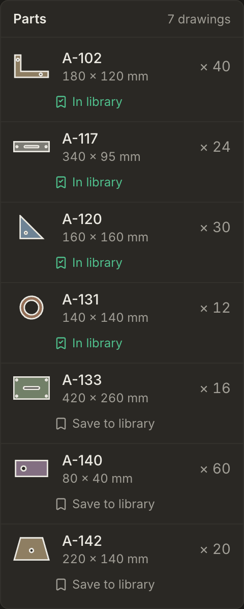
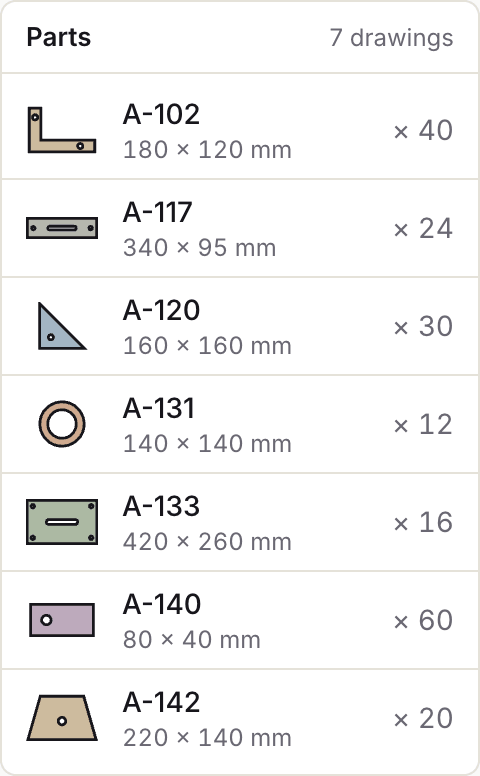
Before you read any note, look at the Parts list. It shows each part's outline, with its holes, and its size in millimetres. If the outline or the size is not what you drew, the file needs work.
| Note on the result | Is the part nested? | Section |
|---|---|---|
| the file could not be read from storage | No | File missing from storage |
| the file could not be read | No | File cannot be read |
| no closed contour large enough to be a part | No | No closed outline |
| n outlines in the file; the largest was nested | Yes, the largest outline only | More than one outline |
| a drawing sheet; the 1:1 outline beside it was nested, not the frame | Yes, the outline beside the sheet | Drawing sheets |
| taken from a view of a drawing | Yes, a view: check it | Drawing sheets |
| w × h mm is wider than any stocked sheet | No | Wider than every sheet |
| n open contours were ignored | Yes, without those lines | Open contours |
| n marking lines (l mm) kept for marking, not cut | Yes, the marking is not cut | Marking lines |
File missing from storage
The note reads: the file could not be read from storage. The part is not nested.
What it means. The drawing was uploaded, but when the nest started, the file could not be fetched from storage. Nothing in the drawing causes this.
Why it happens. A fault between the nester and the file store, on our side.
How to fix it. Start the nest again with the same file. There is nothing to change in QCAD, Fusion, SolidWorks or LightBurn. If the note comes back for the same file, write to us with the file name and the time you uploaded it.
File cannot be read
The note reads: the file could not be read. The part is not nested.
What it means. The file does not open as a DXF. Nest&Quote repairs a damaged file where it can; this note means it could not.
Why it happens.
- It is not a DXF or GEO file. The upload goes by the .dxf or .geo ending, so a DWG, SVG or PDF renamed to .dxf gets through and fails here.
- The file was cut short, by a download or an email attachment that did not finish.
- The program that wrote it does not keep to the DXF format.
Nest&Quote reads DXF R12 and every version from 2000 to 2018, as text or binary, and TRUMPF GEO files. DWG and STEP are not read.
How to fix it. Open the file in your CAD. If the part shows, save it again as a new DXF. If it does not open there either, go back to the drawing it was made from.
- QCAD: open it with File > Open, then use File > Save As and choose a DXF 2000 format.
- Fusion: export the DXF again from the source. For a sketch, right-click the sketch in the browser and choose Save As DXF. For sheet metal, right-click Flat Pattern in the browser and choose Export DXF.
- SolidWorks: use File > Save As, set the type to DXF and, under Options, pick a version from 2000 onwards.
- LightBurn: bring the file in with File > Import. If it opens, save it again with File > Export as a DXF.
No closed outline
The note reads: no closed contour large enough to be a part. The part is not nested.
What it means. Nest&Quote found no closed outline with at least 4 mm² of material, which is a square of 2 × 2 mm.
Why it happens.
- The outline is open. A gap wider than 0.5 mm, or gaps in more than one place, and the outline never closes. We checked this on the engine on 24 September 2026: a 100 × 100 mm square drawn as four lines comes in closed with a 0.3 mm gap at one corner, and comes back with this note with a 1 mm gap.
- A line is drawn twice. An edge drawn twice can stop the outline from closing; see open contours.
- The part is on a skipped layer. Layers for dimensions, text, titles, hidden and centre lines are not read (see how Nest&Quote reads a drawing). An outline on a layer called Sketch1 is never seen, and neither is one drawn with a dashed line type, until you set that layer to Cut under the drawing's line in Not nested (see edit a part).
- The part is not drawn with lines. Hatches, solid fills included, 3D solids, regions and meshes are not read.
- The part is tiny. A closed shape under 4 mm², smaller than 2 × 2 mm, is taken for a stray mark. Checked on the engine on 25 September 2026: a 20 × 20 mm tab is nested, a 1.5 × 1.5 mm square is not.
How to fix it. Find out which of these it is, then:
- QCAD: check the unit under Edit > Drawing Preferences. For a part drawn in inches, either set the unit to inches and save as DXF 2000, or scale the drawing by 25.4 with Modify > Scale and set the unit to millimetres. To move the outline off a skipped layer, select it and pick layer 0 in the Property Editor. Gaps are covered under open contours.
- Fusion: a closed profile is shaded in the sketch, so an outline without shading has a gap. Set the units in the browser under Document Settings > Units to millimetres before you export.
- SolidWorks: for a DXF saved from a sketch, Tools > Sketch Tools > Check Sketch for Feature finds open contours. Set the units to MMGS under Tools > Options > Document Properties > Units before you export.
- LightBurn: Edit > Select Open Shapes shows which outlines do not close. Compare the width and height in the numeric edits toolbar with your drawing.
More than one outline
The note reads: n outlines in the file; the largest was nested. The largest outline is nested, and nothing else.
What it means. The file holds more than one closed outline that could be a part. Nest&Quote nested the one with the most material and left the others out.
Why it happens.
- Several parts were drawn or exported into one file.
- A bare frame came along: a rectangle around the part with no text inside. Nest&Quote cannot tell it from a plate, so it is nested as the part and your part becomes a hole in it. Checked on the engine on 25 September 2026: an A3 frame (420 × 297 mm) with nothing else around a 100 × 100 mm part is nested as a 420 × 297 mm part. With a title block inside, the frame is recognised and left out (see drawing sheets).
- The sketch holds other closed shapes: a construction rectangle, a second part, or a shape drawn inside a hole.
Separate closed shapes under 4 mm² are dropped without a note, so they do not show in this count.
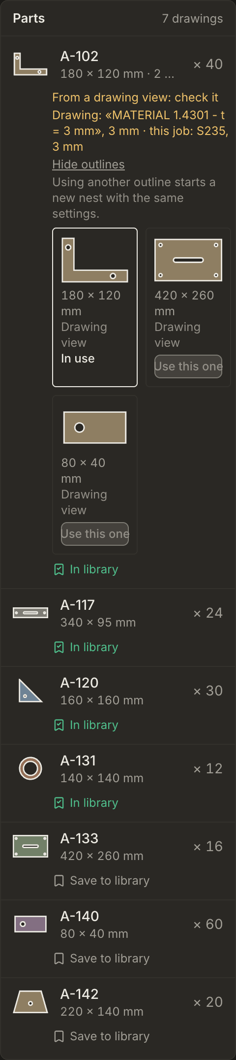
How to fix it. If the right outline is among those found, open Other outlines under the part in the Parts list and choose Use this one. The new nest has the same settings. For the next job, keep one part per file and nothing else in it:
- QCAD: select one part, use Edit > Copy, File > New and Edit > Paste, and save the new file under the part's name. Repeat for each part. Delete the frame and the title block.
- Fusion: create a sketch on the face of the part, use Project on that face only, and save that sketch as a DXF. Export each flat pattern on its own. Export from the sketch or the flat pattern, not from a drawing: a drawing brings its border and title block with it.
- SolidWorks: export from the part, not from the drawing, whose sheet format is a frame. Right-click Flat-Pattern and choose Export to DXF/DWG, or use File > Save As with the type set to DXF and export the face. In the preview, Remove entities takes out anything else.
- LightBurn: ungroup with Arrange > Ungroup if the parts are grouped, delete everything except one part and save it with File > Export as a DXF. Repeat for each part.
Drawing sheets
The note reads either a drawing sheet; the 1:1 outline beside it was nested, not the frame or taken from a view of a drawing. The part is nested in both cases.
What it means. The file is a drawing, not a cut file: a sheet with a frame, a title block, views and dimensions. Nest&Quote leaves out the frame, the title block and boxed views such as the 3D view. Designers often place the flat part at 1:1 beside the sheet, for the laser; when that outline is there, it is the one nested. When it is not, Nest&Quote takes the largest remaining view and marks it From a drawing view: check it.
How to check it. Look at the outline and the size in the Parts list. A view can be the wrong one: a side view, or the view of a tube or a bent part that is not its flat pattern. If it is wrong, open Other outlines and nest again with the right one. If none is right, the file needs a flat pattern.
What the drawing says. Nest&Quote reads material and thickness from the drawing's text, such as LAMIERA AISI 304 - Sp. 3mm or Fe 360 B, and shows it under the part. When it names another material or thickness than the job, the line turns red and the result says which parts differ.
How to fix it. Ask for, or export, the part's flat pattern instead of the drawing:
- SolidWorks: right-click Flat-Pattern and choose Export to DXF/DWG, rather than saving the drawing as DXF.
- Fusion: right-click Flat Pattern in the browser and choose Export DXF.
- QCAD: copy the part's outline from the drawing into a new file and save it under the part's name.
Wider than every sheet
The note reads: w × h mm is wider than any stocked sheet. The part is not nested.
What it means. The shorter side of the part, as read from the file, is larger than the widest sheet in the job less the edge margin on both edges. With a widest sheet of 1500 mm and a 10 mm edge margin, any part whose shorter side is over 1480 mm is left out. The note gives the size Nest&Quote read, in whole millimetres.
Why it happens.
- The unit is wrong the other way. The file says inches, but the numbers were drawn in millimetres, so the part comes in 25.4 times too large. A file that says centimetres over millimetre numbers comes in 10 times too large. Set mm under the drawing's line in Not nested (see edit a part) and nest again.
- A bare frame came along, scaled up to fit around a large part, and was taken for the part. See more than one outline.
- The part is wider than your stock. Then the job needs a wider sheet.
How to fix it. Compare the size in the note with your drawing. If it is 25.4 or 10 times too large, set the unit. If it is the size of your frame, delete the frame. If it is the real size, add a wider sheet to the job if you stock one.
- QCAD: set the drawing unit to millimetres under Edit > Drawing Preferences, save, and check the size again in the result.
- Fusion: set Document Settings > Units to millimetres before you export.
- SolidWorks: set the units to MMGS and export from the part, not from the drawing.
- LightBurn: check the width and height in the numeric edits toolbar before you export.
Open contours
The note reads: n open contours were ignored. The part is nested, without those lines.
What it means. Some lines, or chains of lines, in the file do not form a closed outline. Nest&Quote left them out and nested the rest.
Why it happens. Often it does no harm: centre lines or construction lines on an ordinary layer. Bend lines are recognised and counted instead (see how Nest&Quote reads a drawing), and in a drawing sheet the lines of views and dimensions are expected, so this note is not shown there.
Lines drawn twice and bend lines drawn as ordinary lines no longer break the outline. Checked on the engine on 25 September 2026: a 100 × 100 mm square with one edge drawn twice, the extra line first, comes in closed; a 100 × 50 mm flat pattern with its long edges split at a bend line across the middle, the bend line first, comes in as 100 × 50 mm with one bend.
Sometimes it does harm:
- A hole that does not close is missing. It is not in the nest, the cut length, the pierce count or the price from the nest. Every hole is a pierce; the cut-time calculator shows what that adds.
- An open outer outline lets a hole take its place. The largest closed shape left is a hole, and it is nested as the part. Checked on the engine: a 100 × 100 mm square with a 2 mm gap and a 40 mm hole nests as a 40 mm disc.
How to fix it. Look at the outline in the Parts list. If the size is right, every hole is there and the count matches your bend lines and centre lines, there is nothing to do. Otherwise close the gap in your CAD, delete lines drawn twice, or join the outline into one closed polyline. Nest&Quote closes one gap of 0.5 mm or less per outline, and no more.
- QCAD: zoom into the corners. Snap to end points when you redraw a line, and use Modify > Trim/Extend to bring two lines to a common corner. Draw > Polyline > Polyline from Segments joins connected lines and arcs into one polyline; where it stops short, there is a gap.
- Fusion: an outline without shading has a gap. Drag the loose end onto the other end, or add a Coincident constraint between them.
- SolidWorks: run Check Sketch for Feature on sketches. In Export to DXF/DWG, untick Bend lines if you do not need them in the file.
- LightBurn: Edit > Select Open Shapes shows them. Edit > Auto-Join Selected Shapes joins shapes whose ends touch, Edit > Close Selected Paths with Tolerance closes small gaps, and Edit > Delete Duplicates removes lines drawn twice.
Marking lines
The line reads: n marking lines (l mm) kept for marking, not cut. The part is nested; its marking lines are not cut.
What it means. Lines on a marking layer, such as an engraved part number, an etched logo, a scribed line or a punch mark, belong to the part but are not cut. Nest&Quote keeps them with the part. The Parts list says how many there are and how long (Marking: 2 lines, 220 mm), the nest draws them as thin dashed magenta lines (the legend under the sheet says so), and the nested DXF carries them on a layer of their own, MARK, so your CAM can give them a marking process.
How it is priced. The price panel shows marking as a line of its own, such as Marking, 8.8 m, 2.1 min: the length at a marking speed plus a fixed time for each start (each separate line is one start), at the machine's hourly rate, under the margin on machine time. The speeds are defaults, labelled as such: laser 6 m/min and 0.5 s per start, plasma 5 m/min and 1.5 s, waterjet 2 m/min and 2 s, router 2 m/min and 2 s. A quote gives each part its own marking time, so a marked part costs more than the same part without marking.
Not in the program yet. The cutting paths and the machine programs (G-code) leave marking out, and the program panel says so. Mark from the MARK layer of the nested DXF in your CAM, or by hand.
Which layers count. Layer names that contain mark, etch, engrav, scribe, Gravur, gravier, Markier, Signier, Körn, marcat, incis, marquage or gravure, in capitals or not. Sketch and remark layers are not marking layers. A layer called Beschriftung usually holds text, and text is never cut anyway. A bend layer stays a bend layer, even one called Biegemarkierung. If your marking sits on another layer, set that layer to Mark under the part (see the next section).
Edit a part
Edit part, under each part in the Parts list, opens the drawing as Nest&Quote read it: every line, arc, circle and spline, drawn by what it became.
- Cut: the outer contour in heavy ink over the part's metal, holes in ink.
- Mark: magenta and dashed, as on the nest: marked, never cut.
- Bend line: blue, dash-dot: counted, not cut.
- Ignored: grey and dotted: not read, like dimensions, text, a drawing frame or a line drawn twice.
- Open: dotted in amber: a contour that does not close, so it is not cut.
- Other outline: faded ink: a closed outline that is not this part.
The tools sit on the left, each with its key: Select (V), Cut (C), Mark (M), Bend line (B), Ignore (I), Outer contour (O), Rotate 90° (R) and Units (U). Click a line to select it, or drag a box: from left to right it takes what lies inside, from right to left what it touches. Then give the selection a role. Outer contour picks which closed contour is the part's outside: click one of its lines, and the contours inside it become its holes, even inside a drawing frame. Rotate 90° turns the part before it is nested, for a bent part with a set direction. Units reads the drawing in mm, cm or inch, or with a factor in millimetres per drawing unit: an inch drawing saved without a unit comes in 25.4 times too small until you set inch. Scroll to zoom, drag with the right mouse button or with Space held to pan, and Fit to view (F) brings the whole drawing back.
Under the tools, Layers sets a whole layer at once. Each layer starts with the role its name gives it (by its name); a part drawn on a layer called Sketch1 is ignored until you set that layer to Cut. A layer or a line you set to Cut is cut with all its lines, dashed ones included, and is never taken for a bend line or a loose end.
On the right, the part as it will be nested follows every change: its size, area, weight, cut length, pierces, marking and bends, and what to look at, such as open contours, gaps up to 0.5 mm closed automatically, lines drawn twice and loose ends removed, other outlines and small shapes left out.
Apply and nest again starts a new nest with the same settings and the drawing read your way; the job you came from stays as it is. Nest&Quote reads the drawing again with your changes, so the new nest is the judge. Reset to automatic goes back to how Nest&Quote reads the drawing by itself, and Cancel closes the editor without changing anything. Change setup and nest again keeps your changes.
A drawing that was not nested because Nest&Quote found no closed outline in it, or read it wider than every sheet, has Edit part under its line in Not nested, as long as other drawings of the job were nested.
The rules, one by one
Units in millimetres
Nest&Quote works in millimetres. A file saved in inches, feet, centimetres or metres is converted, as long as the unit is set in the file. A file with no unit set is read as millimetres. DXF R12 cannot store a unit, so an R12 file is always read as millimetres; use R12 only for drawings in millimetres. Checked on the engine: a 4 × 4 in square saved as DXF 2010 with inch units comes in as 101.6 × 101.6 mm, and saved as R12 it comes in as 4 × 4 mm. When the unit is wrong or missing, set it under the part (Edit part) and nest again; there is no need to export the file again.
Closed outlines
Every outline has to close: the outer one and every hole. Draw it as one closed polyline where you can; loose lines and arcs work too, as long as their ends meet. Nest&Quote closes one gap of 0.5 mm or less per outline. A wider gap it leaves open, and it does not guess the missing line.
One part per file
Each file holds one part, and you set its quantity when you upload. The file name becomes the part code, which you can change. Give every drawing its own name: two files with the same part code are treated as one part, with their quantities added and the drawing from the first file used.
No dimensions, text, frames or title blocks
Text and dimensions are skipped. A frame with a title block is recognised and left out, but a bare frame drawn in lines is read like any other geometry. Delete all of it before you export, or export the flat pattern: then what is in the file is what gets nested.
Blocks: no need to explode them
Nest&Quote expands blocks itself, blocks inside blocks included. Explode them anyway if you want to see what a block holds before you upload (in QCAD, Modify > Explode): a block can hide a frame or a second copy of the part.
Splines: fine as they are
Splines, ellipses and arcs are read and followed to within 0.02 mm, so there is no need to convert splines to polylines for Nest&Quote. If the software that drives your machine wants polylines, convert in the export: Fusion's flat pattern Export DXF has Convert splines to polylines, and SolidWorks has Export all splines as polylines in its DXF options.
Cut geometry on an ordinary layer
Put the part on layer 0 or a layer of your own, such as CUT, drawn with a continuous line. Layers for dimensions, text, titles, hidden and centre lines are skipped, and dashed lines are not cut.
Engraving and marking on a layer of their own
Put engraving, etching and scribing on a layer named for it, such as MARK, ETCH, ENGRAVE, Gravur or Markierung. Nest&Quote keeps it as marking: never cut, drawn on the nest, priced as marking time and written to the MARK layer of the nested DXF (see marking lines). On any other layer, closed shapes inside a part are read as holes, whatever their size: text turned into outlines for engraving would be cut out, until you set its layer to Mark under the part.
Questions shops ask
Why does my DXF come in at the wrong size?
Almost always the unit. The part comes in 25.4 times too large when the file says inches over millimetre numbers, and 25.4 times too small when an inch drawing is saved with no unit or as R12. Check the size in the Parts list after the first nest, and set the right unit under the part (Edit part) to nest it again at its size.
Do I have to convert splines to polylines?
Not for Nest&Quote. Splines are read and followed to within 0.02 mm. Your machine's software may want polylines; that is a setting in your CAD's DXF export.
Can I put every part of a job in one DXF?
No. Nest&Quote reads one part per file. From a file with several, it nests the largest and says how many outlines it found; you can choose another one and nest again.
Does Nest&Quote repair my drawing?
Only in small, stated ways. It joins lines and arcs whose ends meet, closes one gap of 0.5 mm or less per outline, drops lines drawn twice, takes a straight line across the outline for a bend line, keeps lines on marking layers as marking, leaves out a recognised drawing frame and title block, expands blocks and repairs a damaged file where it can. It does not redraw a part or guess a missing line. Anything it had to leave out is listed on the result.
Which DXF version should I save?
Any version from 2000 to 2018. R12 works too, for drawings in millimetres only. From TruTops, the GEO file works as it is.
Try it on one of your drawings
Nest a job with your own files and read the Parts list and the notes before anything else. For the checks that run after the nest, see part gap and edge margin. For what goes in and out of Nest&Quote, see DXF input and export.